Pool Projection


Sujith Naapa Ramesh (sn438), Andrew Tsai(aht53)

5/20/2020

Objective


The goal of Pool Projection was to provide a helpful aim assist for pool players in order to sink balls in various states of the gameplay. Pool Projection uses an overhead picture of the pool table to determine the location of the balls and pool cue in the image. Using this information, the program presents how each of the balls would interact if the cue ball was struck at different trajectories.

Introduction


Our initial goal for this project was to provide an overhead aim assist system for pool players that would allow them to improve their game. We planned on having an overhead camera system that would take pictures of the pool table to detect game state and a projector that would display the trajectories of various balls that would occur with each shot. However, because of the Covid-19 pandemic and classes moving online, we were not able to have access to a pool table. So, we decided to implement the software portion of this project using simulated images of a pool table during gameplay. The Pool Projection software accepts images of a pool table with the various balls and pool cue strewn about in various locations, and is capable of detecting the locations of the balls and pool cue, thus determining the various trajectories of the balls with such a shot. In addition, Pool Projection has a Power and Friction mode that represents how the balls would more realistically behave when the cue ball is launched at a certain speed under friction. All of the results of the simulation are depicted onto a Pygame surface on the Raspberry Pi desktop. In essence, we have built a pool physics engine that is capable of presenting users their shot trajectories while also being modular enough to serve as a part of our original vision for this project.

Design and Testing


The first step for our project was accurate detection of pool table elements. Given a pool scenario, in order to project the trajectories properly, the Pi had to know where the balls were located. Our first attempt was to use the OpenCV function HoughCircles to accomplish this. HoughCircles takes an input image and a number of detection parameters, and returns where it detects circles within the image. After a very long period of tuning, we were able to get accurate detection of the balls within a single image (Figure 1). However, we discovered that every time we changed the image (if the balls changed in number or location), we would have to retune the parameters, which was impractical for our planned design since it is supposed to work with any given scenario.

Figure 1: HoughCircles Ideal Implementation

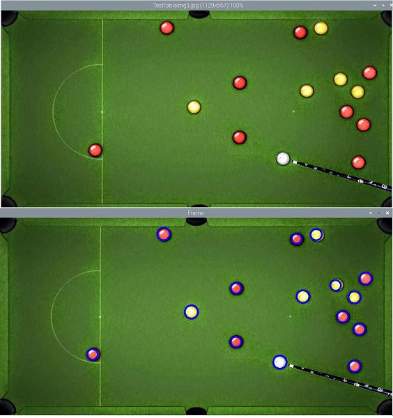
The next attempt was to use contour detection. First, we would take a baseline pool table image, and add features like balls and the cue stick onto the image. Then, we subtract the baseline from the modified image to give a result where only the added images are visible. After taking the grayscale image of the result, cv2.findContours would find where the objects were and draw contours around them (Figure 2).

Figure 2: Contour Detection Process and Output Image

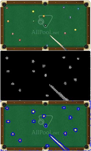
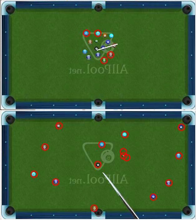
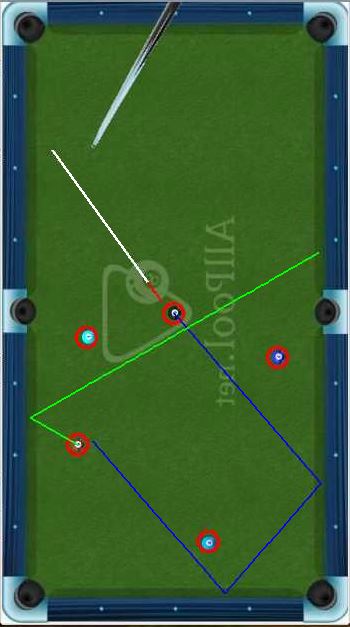
We then process the contours to determine if a given contour is a ball or a cue based on the contour size. By using cv2.minEnclosingCircle() on each contour, we can obtain the (x,y) positions as well as the radius of the smallest enclosing circle for each contour. Based on the radius size, it becomes easy to differentiate between the ball and the cue. We then draw either a circle for balls or a line for the cue on the input image based on the obtained (x,y) positions. Keeping track of the ball and cue positions, we move the image into PyGame, which is where the rest of our functionality comes in. In an image with the cue, we take the endpoints of the contour-based line, and use it as our predicted cue trajectory. Pressing ENTER will then produce a projection line based on the predicted trajectory, simulating the path of a cue ball hit straight on by the cue (Figure 3). If this line collides with any balls on the table, we then use a hard-ball dynamics scheme to determine the collision angle, and the direction that the collided ball will travel.

Figure 3: Cue-based Projection

To determine the angle of the shot to take based on the position of the cue, the change in position along each axis of the image is determined by subtracting the final position from the initial position. Using these two components of the vector we treated as the pool cue, we were able to determine the angle made by the cue in reference to the vertical axis. Based on this angle information, we found the magnitude of the velocity of the cue ball along each axis by multiplying the magnitude of the velocity of the ball by the cosine and sine of the angle previously determined. Using this velocity information, we were able to simulate the cue ball moving along the screen and colliding with objects.

Our dynamics scheme is based on the model given on Professor Bruce Land’s ECE4760 page (see References and Code Snippet 2 in Appendix below). The projections are timestep-based, where in each iteration of the loop the projection moves forward slightly at a certain “velocity”; the balls begin at rest. In each timestep, the ballCollision function loops through each known ball, and if the current trajectory would cause a collision with a ball in the current timestep, then it would return the index of that ball. Given the index, the main loop can recognize that there is a collision, and from the (x,y) position of the collided ball, can calculate the radial distance and “velocity” difference between the current position and the collided ball. Then, that information is combined to form the dot product between distance and velocity as well as the squared distance magnitude. The dot product multiplied by the x (y) distance divided by the magnitude gives change in x (y) velocity. There is an important point to highlight here: after a collision with a ball, the collided ball is the new “tracked” ball, and the trajectory of the previous ball is no longer tracked. Thus in the code we remove the collided ball from the array of tracked balls. This is mainly to prevent the issue of multiple overlapping collisions; normally when using this dynamics model after each collision there must be several timesteps where collisions are ignored in order to prevent collision overlap issues. The method we use circumvents that problem with minimal impact to the resulting simulation.

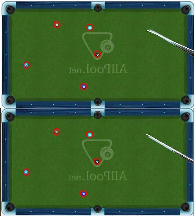
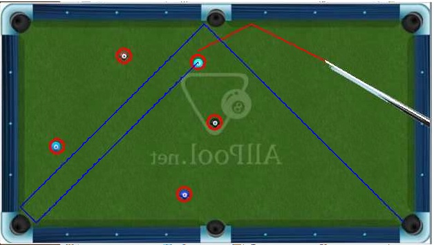
In addition to the projection line from the cue, we also added the functionality of placing a cue anywhere on the table. By clicking on two points, a virtual cue is placed between those points, and hitting ENTER will give the projection of the shot from the virtual cue. This would allow players to visualize shots from any position and any angle on the table, and allow us to give projections for images where a cue is not present within the image (Figure 4).

Figure 4: Virtual Cue Projection

Our last added functionality is an additional mode where velocity, shot power, and friction are taken into account. After determining the cue position, the shot power can be input (between 1 and 10), which determines the starting velocity of the cue ball projection. With each animation timestep, the velocity decreases by a “friction” factor, and the simulation ends when the velocity has decreased such that the ball no longer seems like it is moving. The purpose of this mode is to be able to more closely simulate the real-life movement of the balls across the pool table, since shot power and friction are very important physical aspects that players must take into account.

Results


Overall, the various components of the program fit together nicely to provide a cohesive product. The ball and cue detection worked fairly in most cases and could provide bounding regions around these game elements. The locations of the game elements could then be detected and using this information, game state could be simulated. However, there were some issues during the ball detection case that would cause the system to fail (Figure 5). Sometimes, the locations of the centers of the balls would be slightly offset while in other cases, there would be false positives in the image. Other times, when the balls would be too close together on the table, the contours would overlap just enough for the ball center detection to be off.

Figure 5: Detection Failures

The main culprit for this host of issues was the lack of resolution in the images we used. We were limited in the resolution of the images we could use for this project because we needed an undistorted overhead picture of an empty pool table upon which we could populate images of balls and pool cue in various positions. Since the availability of such images in high resolution was limited we could only use a lower resolution image. Our belief that these issues stem from image resolution is tied to how the medium in which we uploaded these images to the Pi affected our ball detection quality. When we used higher quality mediums of image transfer like Google Drive, the number of false positives reduced tremendously compared to lossy mediums.

Sometimes, we had issues with drawing a line on the pool cue in certain situations when the pool cue was further up into the table. This is because the pool cue detection algorithm uses the detected contour to draw a bounding rectangle around the contour, and the initial predicted cue trajectory is based on the corners of the rectangle. However, this would not actually match the true cue trajectory since the line would not be aligned with the center of the cue. We attempted to solve this by manually shifting the line positions based on where the cue was in the image (Figure 6), which to some extent was an effective solution but is still not completely robust.

Figure 6: Original and Rectified Cue Line

Also, during the ball collision simulation, if the balls moved too fast, then the radii of the ball would overlap at the timestep of their collision as opposed to just touch. In this case, the trajectory of the ball collision shifts slightly from what would be expected in real life. This issue becomes more apparent when the radii overlap more which would happen at higher speeds. However, this is mostly an edge case and should not be too much of an issue in most situations.

Conclusion


In conclusion, the project was fairly successful in terms of the objectives that we set out. Pool Projection is capable of detecting gamestate from the image of a pool table and uses this information to predict the realistic trajectory of the balls. Furthermore, more advanced modes like Power and Friction are capable of depicting realistic start and stop points of the balls after being struck at various velocities.

The one piece of the implementation that we could not get working was the use of a camera. The initial plan for the project relied on the use of a camera to get the overhead image of a pool table but that proved to be infeasible as we did not have access to a pool table. We then planned on trying to use the camera to take a picture of a printout of a pool table, but that did not seem to provide a realistic basis for implementing the rest of the software. In addition, the low resolution images of the pool table we ended up having to use would have not translated well with a camera capture of any resolution. As a result, we decided to save camera incorporation for future work on the project.

Future Work


The biggest area of future implementation that we would focus on is making our current model compatible with an actual pool table setup. This would require camera and projector integration with our current project, but the rest of our current functionality has the potential to work quite well with real-life images and projection. The camera could just take a picture of the empty pool table as the baseline image, then as the game goes on it would take the current game state as the modified image, from which it would be able to grab contours and subsequently the positions of all the game elements. Improvement on the detection algorithms would be necessary to reduce the likelihood of false positives and support detection of balls that are clustered together. Also necessary is finding a robust solution to lining up the cue line with the actual cue center. However, with those improvements and using a good camera setup, detecting elements on a real pool table and giving real-time trajectory predictions should be very feasible given our progress so far on this virtual model.

There are also numerous software improvements and features we could add to our model, depending on the direction we want to take with it. Integration of the pool table pockets into the projections is one possibility; right now we just treat the pocket zones as walls, but realistically if a ball is projected to fall into a pocket the simulation should end at that point. For even more realism, the cue ball itself could become a factor in the calculations; for example, if we modeled the cue ball separately from the cue stick, it would in theory be possible to model the spin and curving effects of striking the cue ball on one of the sides rather than dead center.

Budget


This project only required a Raspberry Pi which was provided by the class. So, we did not need to spend any money on the project.

Work Distribution


Andrew Tsai

Experimentation with HoughCircles, integrating with PyGame, ball dynamics modelling (including input power and friction-tracking modes) and animation

Sujith Naapa Ramesh

Research and implementation of contour detection, development of image pre-processing procedure, implementing projection line code

Code Appendix


1. Ball and Cue Detection

2. Ball collision